Logic Systems
- The Logic System is formed by the logic elements on the manifold, which have compound functions according to the hydraulic circuit formations of the host machine.
Features
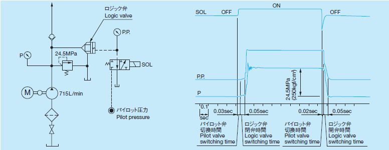
- Shockless switching of the high pressure/large capacity hydraulic circuit. (Fig.1)
- High speed and high frequency switching ability. (Fig.1)
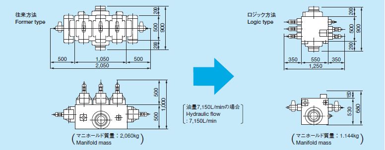
- Simple the hydraulic system and easy maintenance. (Fig.2)


Logic Systems Application
- This logic system has freedom for design and can form various circuits by using each logic element's function and their controlling method.We not only produce, but also design logic systems to meet your requirements.
Logic Element
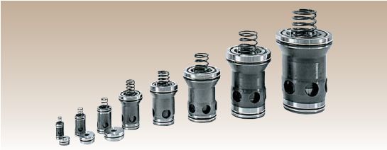
- Various control by combining logic elements and logic valve covers.

Logic Element for Pressure Control
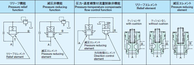
- The pressure controlling logic elements have a relief valve element and a pressure reducing element. Through combination with the directional controlling elements, they can form a more advanced logic system.
Features
- Pressure override as a relief valve element.
- Pressure reduction of the large capacity flow, which standard valves are unable to control stably.
- Forms a pressure compensating flow control element through combination with flow control valve.

Contact
If you need more information about our business,
please feel free to contact us.


