Pursuing Safety and Low Fuel Consumption Gears at the Core of Next-Generation Aircraft

Associated with global warming and rising fuel prices, aircraft should consume less fuel, generate less noise, and ensure greater safety than ever before. The drivers of the new aircraft industry trends are the prominent European and US manufacturers Airbus and Boeing. However, in terms of gears, Kawasaki is the global leader and consistently introduces technological innovations. Without novel gears, there would be no next-generation aircraft. This article features the aircraft gear business of industry leader Kawasaki and its advanced technologies.
Gearboxes—Crucial in Many Industries Kawasaki’s Pride in its Variety of Gear Products in the Aviation Industry
The gearbox adjusts the rotational speed and torque (force causing rotation) through different combinations of internal gears. The use of a gearbox can increase the torque and speed in order to transmit mechanical power. Gearboxes are vital in many industries, and their applications include vehicle transmissions, reduction gearboxes of Ferris wheels, and speed-up units at the heart of wind power generation.
In the case of aircraft, gearboxes serve two roles: efficiently convert engine rotation into the desired speed as the principal function and to recover rotational energy as the power generator. Gearboxes must provide great reliability with no failures during prolonged operation and minimize vibrations and noise while achieving smooth power transmission. In addition, high transmission efficiency that reduces the heat generated by gear contact and high transmission power density to pass through large power with a lightweight body are also important.
Kawasaki now boasts of the industry’s most extensive lineup of aircraft gear products, including transmissions for the BK117 and other helicopters, accessory gearboxes (AGBs) for airplanes, and proprietary power generation systems for aircraft (T-IDG™). The aircraft gearbox manufacturer is at the world's top tier.
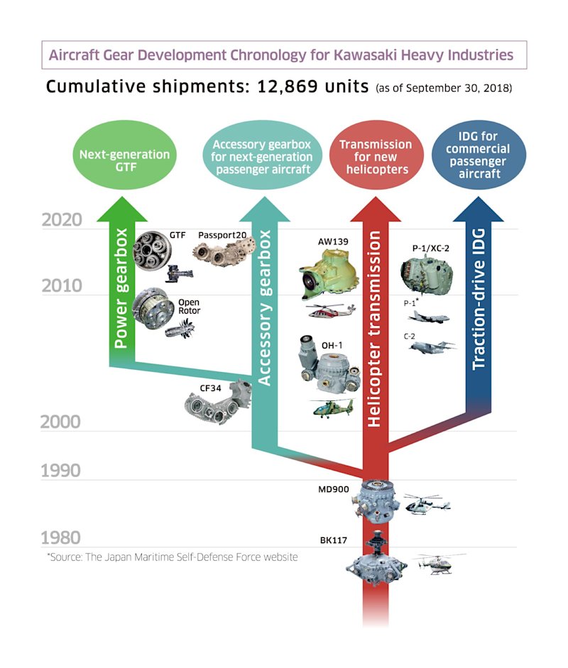
Kawasaki’s aircraft gear business is rooted in the development of helicopter transmissions that started with a project to develop an in-house helicopter in the 1960s. In a joint project with Messerschmitt-Bölkow-Blohm (present-day Airbus) that began in 1977 for the BK117 helicopter, Kawasaki was tasked with the development of the most critical component—the transmission system. Thanks to its excellent performance and safety features, the series has been adopted widely by police, firefighting, media, and emergency medical services. Based on the masterpiece that demonstrated excellent reliability and durability, Kawasaki successfully expanded the aircraft gear business.
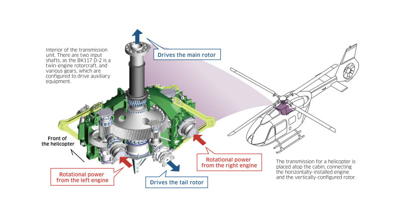
The helicopter transmission is installed atop the cabin and performs the following operations: (1) steps down the speed and then transfers power from the engine to the main rotor (rotor blade) and the tail rotor, (2) drives the accessories, and (3) transfers the lift generated by the main rotor to the helicopter body and receives the force of the thrust and drag, which opposes the direction of movement.
According to the verification of the eighth-generation model of the BK117 D-2 series, the transmission steps down the engine speed of 6,000 rpm to 380 rpm (a reduction ratio of about 16:1) and, at the same time, increases torque to 19,600 N・m to drive the main rotor. This remarkable torque capacity is sufficient to revolve two passenger cars attached to the end of a one-meter-long bar.
More specifically, while the pair of engines generates a total of 1,000 horsepower, the spiral bevel gears of the transmission change the direction of the rotary motion by 90 degrees and simultaneously reduce engine output speed. Then, a helical gear in the second stage synthesizes the two systems of motion and decreases the rotational speed again, resulting in the optimal rotor speed. Other products from Kawasaki use compact planetary gears, which can achieve a weight-to-horsepower ratio (weight divided by net horsepower) of less than one-half of an automobile transmission.
Kawasaki designed this reliable gearbox, which was compact enough to be installed on the ceiling and led to a roomier cabin. As a result, clamshell doors became possible. It is one of the reasons the helicopter earned the confidence of professionals to play an active role in emergency medical, police, and firefighting services dispatched for emergencies.
From Machining to Final Inspection Technology to Reduce Gear Weight to the Maximum
Because the demand is for the gears of aircraft to be more lightweight, engineers are working to provide the utmost in thinning without compromising durability. The gears can be as thin as 2 mm yet nevertheless transfer a tremendous amount of power. Gears with holes to lighten the weight are prone to deformation, yet the tooth shape must be accurate to the level of micrometers (μm, which equals 1/1000 millimeter).
Masahiro Gouhashi of the Production Engineering Division states, “The way gears deform varies, depending on the shape and type of machining process. Therefore, the key to producing accurate gears is minimizing and correcting deformations so that the complex, delicate shapes the designers first envisioned can be achieved.”
In gear production, the first step is to cut a round gear blank using special machining equipment with a cutter that is precisely the same shape as the desired teeth. The gear then undergoes the carburizing and quenching process through which the gear surface absorbs carbon and hardens, followed by a grinding process with dedicated machine tools whereby the teeth are ground to a micrometer level of precision. Finally, to improve resistance to fatigue, small steel beads are blasted against the surface in a process called shot peening. In the inspection process, several nondestructive tests are performed. These include nital etch testing, which uses a special chemical solution to make sure that the strength of the gear has not decreased from the temperature increases during the machining and grinding processes, and magnetic particle inspections, which magnetizes the gears to detect micro-cracks on the surface that cannot be found in a conventional visual inspection.
Speaking of the comprehensive capabilities Kawasaki exhibits, Gouhashi says, “The most notable feature of our aircraft gear manufacturing is that we possess expertise encompassing the entire process of gear manufacturing from machining and heat treatment to final inspection, and we make sure that no defects in hidden areas go undetected. In the aircraft gear sector, this comprehensive expertise is what gives us a competitive edge in the global arena.”
Toward the Achievement of 60-Minute Loss of Lubrication (LOL) Operation of Helicopters Pursuit of Transmission Safety
The development of helicopter transmissions requires precision and performance of the individual gears as well as the gears as a unit component of the helicopter. This includes the development of gears to handle engine power at faster rotational speeds and greater horsepower and mechanisms to minimize the vibration that light, thin gears are likely to generate.
One of the demands on helicopter safety is LOL performance of the transmission, which allows the aircraft to continue to fly after the loss of the lubricant in the transmission that lubricates and cools the gears and bearings. Civil aviation must have a 30-minute LOL capability. However, even longer flight under LOL conditions is necessary to ensure safe aircraft operation, especially for the transportation between offshore oil fields and onshore terminals that has been increasing in recent years.
According to Kenta Ogasawara of the Commercial Engine Project Division, “Improved technology provides a good outlook for Kawasaki to achieve a 60- to 70-minute LOL capability, and a demonstration test is planned for the end of fiscal 2018.”
The key to achieving such duration is cooling. The transmission configuration, structure, and materials that will preclude overheating and the seizing of gears and bearings after the loss of lubricant are being investigated. Moreover, Kawasaki developed a simulation technique in combination with computational fluid dynamics (CFD) and heat-transfer analyses to reproduce the temperature changes in transmission gears after LOL to optimize gear shape and the bearing arrangement. “We hope that this technology will lead to future transmission development with innovative concepts,” adds Ogasawara.*1
*1: For the descriptions above, see Kawasaki Technical Review No. 179, “Technical Description-Advancement of Aircraft Gearbox Design Technology.”
Realization of Lightweight Body with Advanced Control, High Efficiency and Great Durability Development of the Innovative Power Generator T-IDG™
Auxiliary power supply units provide electricity for lighting, announcement systems, cooking, and other operations when the aircraft is on the ground and the engine is stopped. Once the engine starts, an alternating current (AC) electric power generator driven by the aircraft engine is activated, making the switch from the auxiliary power supply unit. The rotational speeds of aircraft engines vary before and during takeoff as well as in flight. Since the generator is connected to the engine, generator rotation also changes with engine operation, which leads to varying frequencies of generated power and results in unstable power supply.
This is the reason the generator is unified with a constant-speed drive (continuously variable transmission or CVT) called the integrated drive generator (IDG), which is installed on the accessory gearbox of the engine, to run the generator at a constant speed regardless of the engine speed.
The accessory gearbox is a module powered by the engine main unit to drive the generator, lubricant pump, fuel pump, and hydraulic pump.
Kawasaki’s unique technology was used to develop the T-IDG, the constant-frequency power generator for aircraft involving a high-speed traction-drive CVT, which was the first in the world to be applied as an airplane constant-speed drive unit. The T-IDG houses a traction-drive CVT to regulate the varying drive rotational speed of the engine and operates the generator at a constant speed so that the aircraft always has AC power at the same frequency (400 Hz).
The traction drive mechanism transmits power with the use of the viscous resistance of the oil film. While orthodox IDGs are commonly equipped with a hydraulic CTV, the T-IDG utilizes special oil viscosity to transmit power, which reduces the losses compared to conventional hydraulic systems and achieves better durability because there is no contact friction between parts. This innovative CVT is not as heavy as hydraulic ones and realizes advanced efficiency, durability, and controllability.
Lightweight aircraft bodies and high-efficiency engines have always been in demand by the aviation industry since before global warming was acknowledged as a problem. In addition, electric vertical takeoff and landing (eVTOL) aircraft, which are known as “flying cars” for new intercity mobility, are about to appear, and the development of electrification technology for aircraft is being addressed from both the viewpoints of engines and accessories. In other words, electrified accessories (more electric aircraft, MEA) and a power generation system with greater capacity are needed for future aircraft. Kawasaki is accelerating its efforts to develop the T-IDG for greater capacity in order to introduce products into the commercial aircraft market.
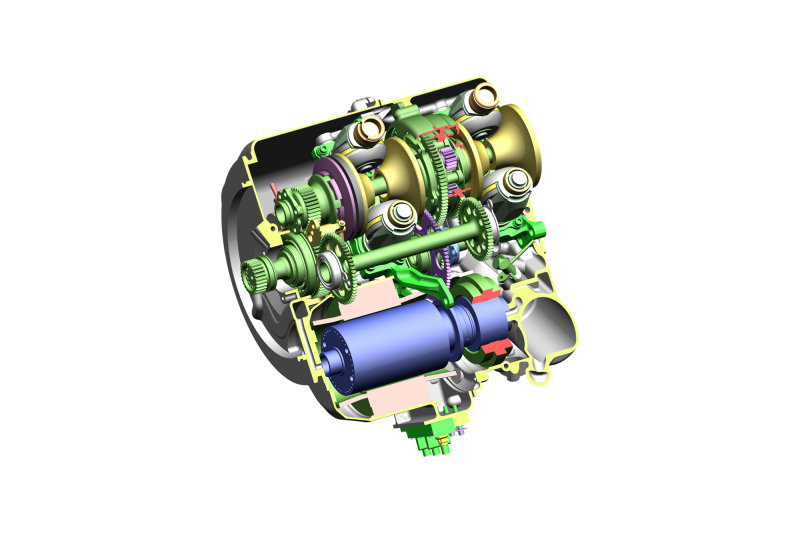
● AC power generator (output: 90 kW): Producing electricity at 24,000 rpm, the AC generator supplies stable frequency power to all equipment on the aircraft for maximum safety. * Each aircraft engine is equipped with its own power generator. In the event something goes wrong with a generator or an engine, the other power generators serve as backups to ensure power to the aircraft.
● Output terminal: Electric power is delivered from here.
Source: Kawasaki News 162 (English Version: Scope 88) “How the Innovative T-IDG™ is Taking Aircraft Electric Power Supply to New Heights”
Fan Drive Gear System (FDGS) is the Heart of New Engine for Lower Fuel Consumption, Lower Noise, and Lower Emission of CO2 and NOx
Kawasaki has partnered with Pratt & Whitney (P&W) to develop advanced engine systems.
The modern aircraft principally employ jet engines. A jet takes in air from the front of the body, compresses it, sends the air to the combustion chamber to raise the temperature and pressure, and spouts it from the exhaust ports.
The jet engine mechanism has these four processes: intake, compression, combustion, and exhaustion. Jet engines are categorized into two types: turbojets for combat fighters and turbofans for passenger airplanes.
The turbojet only exhausts the compressed gas that has passed through the combustion chamber. Conversely, in order to improve fuel consumption, the turbofan uses the air taken in by operating a fan and the compressed air from the combustion chamber, and both are then ejected backward from the body to generate thrust. The former is called bypass air because it does not go through the combustion chamber.*2
On the foundation of conventional turbofan engines, P&W developed a geared turbofan (GTF) engine where the planetary gear mechanism was introduced to drive the fan at lower speeds.
In general, the fuel efficiency of turbofan engines improves with a larger fan diameter, in other words, when the bypass ratio increases. However, the rotational speed of the fan and the ideal setting of the turbine and compressor to drive the fan is different, which limited improvements in performance.
The breakthrough in this stalemate was the GTF engine, which has a gearbox between the fan and the turbine that allows each component to work at its optimal speed.
*2: See NEWSWITCH “[Series] Understand the Basics! MRJ (3) -GTF Engine.”
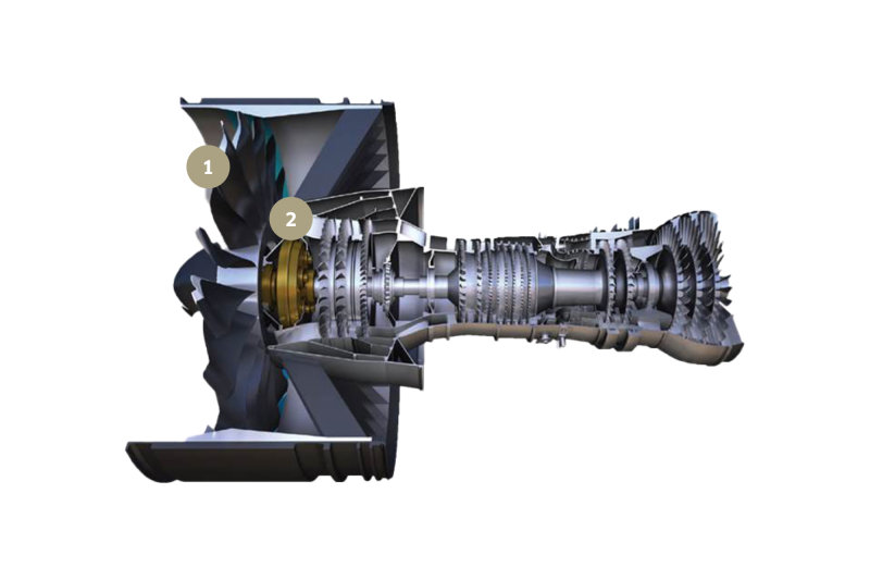
Source: Kawasaki Technical Review No. 179 “New Product Introduction-Regional Jet Engines PW1500G and PW1900G”
Kawasaki participates in P&W’s development and production program for the PW1500G and PW1900G engines as their next line of regional jet planes (aircraft integrated with turbofan engines for short-distance transportation) and is responsible for the combustor and the fan drive gear system (FDGS), which are critical components in this unprecedented engine.
The FDGS uses a planetary gear system to accommodate its coaxial input and output shaft design, as well as to make it more compact and lightweight. The engine is also designed to produce 20,000 horsepower (hp), which far exceeds the engine output of helicopters, and must attain reliable operation for more than 30,000 hours.
Kazuhiro Sato, who leads the development project, comments, “With such huge horsepower, even a 1% loss of energy, about 200 hp, will generate 150 kW of heat. This not only compromises the most important factor-fuel efficiency-but also poses serious challenges involving the coolant oil and the weight and size of heat exchangers.”
This is why, in addition to being lightweight and compact, the FDGS must be designed to minimize losses from gear friction and oil churning.
Sato explains, “Oil and gas mix and flow in a very complex way inside the FDGS, and Kawasaki possesses the world’s most sophisticated technology to computer simulate this flow. Moreover, the company has invented a proprietary technique that optimizes the flow and maximizes the lubrication and cooling effects. As a result, an energy efficiency of 99.6% has been achieved.”
By incorporating the FDGS, P&W’s GTF engines, the PW1500G and PW1900G, have realized a high bypass ratio, improved fuel efficiency by 16%, decreased noise by 75%, and significantly reduced CO2 and NOx emission compared to the previous models. They will be mounted on the regional jet planes of Airbus and Embraer, and the initiation of mass production is scheduled.
Sato adds, “Kawasaki’s proprietary technologies were all developed in conjunction with the Corporate Technology Division during a research project to develop a gear system for open rotor engines whose commercialization is expected to take place after 2030: in other words, in an engine development project already focused on the next generation of engine after GTF engines. Based on the expertise gained, we would like to continue to upgrade our technological prowess and propose further innovations.”*3
*3 See the press release of Kawasaki Heavy Industries “Delivery of First Kawasaki’s FDGS for PW1500G Regional Aircraft Jet Engine for Pratt & Whitney,” and Kawasaki Technical Review No. 179 “New Product Introduction-Regional Jet Engines PW1500G and PW1900G.”
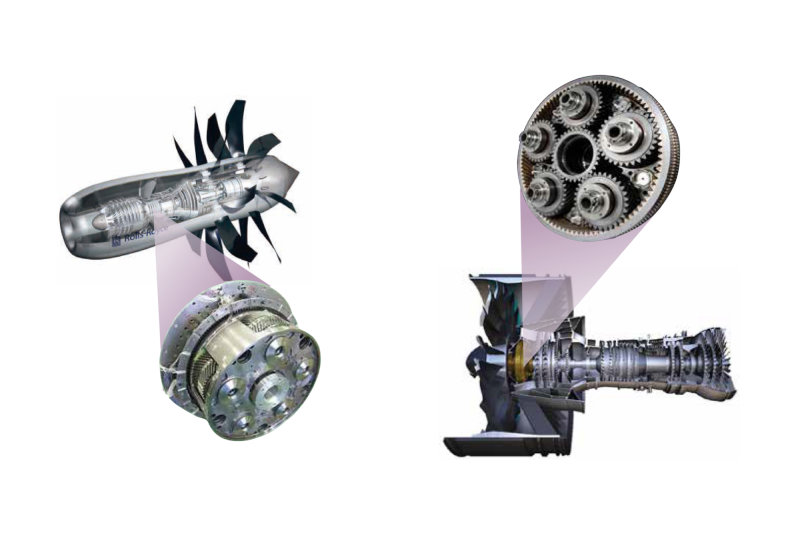
Even though the gear technology for aircraft transmissions and FDGS is essential, it is not noticeable compared to engines. However, the low fuel consumption and improvement in aircraft safety are not feasible without superior gears. Unconventional gear technology is crucial for realization of the next generation of aircraft, and gears are, indeed, at the core of aircraft technology. Developing and manufacturing aircraft gears, Kawasaki, the world’s leader, establishes technological innovation that is leading the trend of the new era.

Gear System Technology
Aerospace Systems Company
Kawasaki Heavy Industries, Ltd.
Aiming to Become the Dominant Player in the Global Aviation Market by Leveraging Our Aircraft Gear Technologies
Fundamentally, gears are used for efficient transfer of energy. The more we try to enhance that efficiency, the more important the roles of gears become. They are parts that demonstrate The aircraft gear business at Kawasaki was launched with the licensed production of helicopter transmissions. After that, in conjunction with the Corporate Technology Division, the Aerospace Company tackled various challenges to develop unbeatably high-performing and reliable products based on proprietary technologies. These achievements are attributable to our integrated manufacturing process, covering all phases from development to manufacturing, and allowing the sharing and solving of problems that arise in between phases. A proactive corporate culture that has encouraged engineers to take on new challenges was another contributor.
As a result, technologies originally associated with helicopter transmissions have evolved to a level that is now applicable to the accessory gearboxes that drive auxiliary equipment, the traction-drive integrated drive generator (T-IDG™) that is driven by the aircraft engine to generate electrical power, and now, future technology-the FDGS. These technologies are indispensable to the operation of aircraft, and, considering the future growth of the aviation industry and the expansion of gear applications (“gearification”*), our gear business has great potential for growth and is expected to become one of the pillars of the Aerospace Systems Company.
In the aircraft sector, continuous efforts are being made to reduce fuel consumption and emissions, and eventually there will come a time when more advanced GTFs, open rotor engines, and other next-generation engines are the only options. Even when such trends become prevalent, gears will still be pivotal parts. Without gears, there would be no next-generation engines.
The drivers of new aircraft industry trends are prominent U.S. and European manufacturers. However, in terms of gear technology that can turn these trends into reality, or which serves as the backbone of innovation and demonstrates great potential in creating technological breakthroughs, Kawasaki is the world leader. In my opinion, it is not an overstatement to say that Kawasaki’s technological innovations drive forward the new trends. Indeed, those who rule the gears, rule the world.
*3: “Gearification” is a term coin ed to mean “using gears to drive fans.”

Engine Production Engineering Section 1
Engine Production Engineering Department
Production Engineering Division
Aerospace Systems Company
Kawasaki Heavy Industries, Ltd.

Drive System Engineering Section 1
Drive System Engineering Department
Commercial Engine Project Division
Aerospace Systems Company
Kawasaki Heavy Industries, Ltd.

Drive System Engineering Department
Commercial Engine Project Division
Aerospace Systems Company
Kawasaki Heavy Industries, Ltd.
Note: The numerical values and job titles stated herein are based on information as of October 2018.
![]() Energy and Environment
Energy and Environment![]() Energy and Environment
Energy and Environment

